I Beam Standard Sizes: A Comprehensive Guide
Navigating I-beam standard sizes requires readily accessible PDF resources, detailing dimensions and properties․ These charts offer crucial specifications for structural engineering projects,
ensuring accurate material selection and safe, reliable construction outcomes․
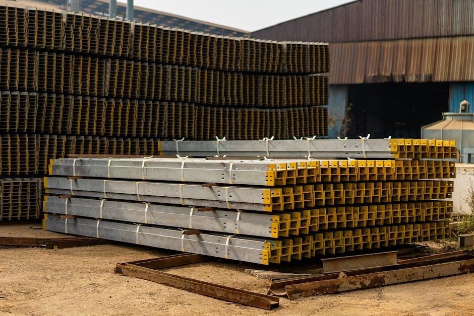
I-beams, fundamental to modern construction, are hot-rolled structural steel components characterized by their distinctive I-shaped cross-section․ Their design maximizes strength and minimizes weight, making them ideal for a wide array of load-bearing applications․ Understanding I-beam standard sizes is paramount for engineers, architects, and construction professionals․

Accessing comprehensive I-beam standard sizes PDF documents is crucial for accurate project planning․ These resources detail critical dimensions – depth, flange width, and thickness – alongside essential properties like section modulus, moment of inertia, and weight per foot․
These PDFs often categorize beams by designation (e․g․, W-shapes, S-shapes) and material grade, facilitating precise material selection․ Furthermore, they provide vital information for calculating load capacity and ensuring structural integrity․ Properly utilizing these charts ensures compliance with building codes and safety regulations, leading to robust and durable structures․ Availability of these resources streamlines the design and construction process․
What are I Beams?
I-beams, also known as H-beams, are structural steel profiles possessing an “I” or “H” shaped cross-section․ This configuration optimizes the beam’s ability to resist bending, making them exceptionally efficient for horizontal support․ The vertical webs handle shear forces, while the horizontal flanges resist bending moments․ They are widely used in building frames, bridges, and other load-bearing structures․
Detailed I-beam standard sizes PDF charts are essential for identifying the appropriate beam for a specific application․ These documents outline precise dimensions, including depth, flange width, and web thickness, crucial for structural calculations․
Understanding the nomenclature within these PDFs – such as W6x25 denoting a 6-inch deep beam weighing 25 lbs/ft – is key․ Accessing these resources allows professionals to select beams that meet load requirements and adhere to safety standards․ Properly specified I-beams contribute to the stability and longevity of any construction project, ensuring structural soundness․
Common I Beam Materials
I-beams are predominantly manufactured from structural steel, with several common grades available․ Carbon steel (A36, A992) is frequently used due to its balance of strength, weldability, and cost-effectiveness․ High-strength, low-alloy steels offer increased yield strength for applications demanding greater load capacity․ Stainless steel I-beams provide corrosion resistance, ideal for harsh environments․
I-beam standard sizes PDF documents typically specify the steel grade alongside dimensional data; These PDFs are vital for verifying material properties, ensuring compatibility with design specifications and relevant building codes․ Understanding the material’s yield strength, tensile strength, and elongation is crucial for accurate structural analysis․
The choice of material impacts the beam’s performance and longevity․ Accessing comprehensive PDF charts allows engineers to select the optimal steel grade based on load requirements, environmental conditions, and budgetary constraints, guaranteeing a safe and durable structure․
Understanding I Beam Nomenclature
I-beam nomenclature is crucial for accurately identifying and specifying the correct size and properties․ American standard beams utilize a designation like “W12x26,” where ‘W’ denotes a wide flange shape․ The ‘12’ represents the nominal depth of the beam in inches, and ‘26’ signifies the weight per foot in pounds․
I-beam standard sizes PDF charts detail these designations, alongside corresponding dimensions like flange width, flange thickness, web thickness, and overall height․ Universal beams (British/European standards) use ‘UB’ followed by a numerical designation indicating depth and weight․
Decoding this nomenclature, often found within PDF specifications, allows engineers to quickly ascertain a beam’s load-bearing capacity and suitability for a specific application․ These charts also clarify variations in steel grade and manufacturing standards, ensuring precise material selection and structural integrity․

American Standard I Beam Sizes
American standard I-beams, detailed in readily available PDF charts, are designated by the ‘W’ shape, indicating wide flanges․ These resources provide crucial dimensions and weight specifications․
Wide Flange Beam Designation (W-Shape)
Understanding W-shape designations is fundamental when working with American standard I-beams․ These beams, commonly found in structural engineering PDFs, are identified by a ‘W’ prefix followed by two numbers – for example, W6x25․ The first number represents the nominal depth of the beam in inches, specifically the height of the vertical flange․
The second number indicates the weight of the beam per foot, rounded to the nearest pound․ Therefore, a W6x25 beam is approximately 6 inches deep and weighs 25 pounds for every foot of its length․ PDF specification sheets are invaluable for confirming these details, as actual dimensions can vary slightly due to manufacturing tolerances․
These designations allow engineers and builders to quickly identify the appropriate beam size for a given application․ Comprehensive I-beam size charts in PDF format typically list a wide range of W-shapes, along with their corresponding dimensions, section properties, and material specifications․ Accessing these resources ensures accurate material selection and structural integrity․
W-Beam Dimensions: Depth (D) and Weight (W)
W-beam dimensions are primarily defined by two key parameters: Depth (D) and Weight (W), both readily available in detailed I-beam standard sizes PDFs․ Depth, typically expressed in inches, refers to the overall height of the I-beam from the top of the upper flange to the bottom of the lower flange․ This dimension is crucial for determining load-bearing capacity and structural stability․
Weight, indicated in pounds per foot (lb/ft), represents the mass of a one-foot length of the beam․ It’s a direct indicator of the steel quantity used and influences the beam’s strength and cost․ PDF specification sheets provide precise values for both Depth and Weight, alongside other critical dimensions like flange width and thickness․
Understanding these dimensions is vital for accurate structural calculations․ I-beam size charts within PDFs often present this information in tabular format, facilitating quick reference and comparison between different W-beam sizes․ Always consult official documentation for precise specifications before commencing any construction project․
Common W-Beam Sizes and Their Properties
Common W-beam sizes, comprehensively detailed in I-beam standard sizes PDFs, include W6x9, W8x10, W12x15, W14x30, and W18x36․ Each designation indicates the nominal depth (in inches) and weight (in pounds per foot) of the beam․ These are frequently used in various construction applications, from residential framing to large-scale industrial projects․
PDF resources outline key properties for each size, including section area, section modulus (S), and moment of inertia (I)․ Section area defines the cross-sectional area of the beam, while the section modulus indicates its resistance to bending․ Moment of inertia reflects the beam’s stiffness and resistance to deflection․

I-beam specification charts within these PDFs also provide information on radius of gyration and theoretical weight per foot․ Accessing these detailed properties is crucial for engineers and designers to select the appropriate W-beam for specific load requirements and structural designs, ensuring safety and efficiency․

Universal Beam Sizes (British/European Standards)
British and European standards utilize Universal Beams (UBs), with specifications detailed in readily available I-beam standard sizes PDFs․ These documents outline dimensions and material grades․
Understanding Universal Beam (UB) Designation
Universal Beam (UB) designation, crucial for interpreting I-beam standard sizes PDFs, follows a standardized naming convention․ Typically, a UB designation begins with “UB,” signifying a Universal Beam manufactured to British Standards (BS 4-1:2005)․ This is followed by a numerical value representing the nominal depth of the beam in millimeters․
For example, a “UB 200” indicates a beam with a nominal depth of 200mm․ However, the actual depth may slightly differ from this nominal value․ Further details, including flange width, flange thickness, and web thickness, are found within comprehensive I-beam standard sizes PDFs․ These PDFs provide detailed tables outlining the precise dimensions for each UB size․
Understanding this designation system, alongside referencing detailed PDFs, is essential for engineers and construction professionals․ It ensures accurate material selection and proper structural calculations․ The weight per meter, section modulus, and moment of inertia are also readily available within these standardized documentation resources․
UB Beam Dimensions: Depth, Flange Width, and Thickness
UB beam dimensions – depth, flange width, and thickness – are critical parameters detailed in I-beam standard sizes PDFs․ Depth (D) represents the overall vertical height of the beam, a primary factor in bending resistance․ Flange width (B) dictates the horizontal extent of the top and bottom sections, influencing stability and load distribution․
Flange thickness (Tf) and web thickness (Tw) are equally important․ Thicker flanges enhance bending capacity, while web thickness resists shear forces․ I-beam standard sizes PDFs present these dimensions precisely, often in millimeters, for each UB section․ These charts also include tolerances, acknowledging slight manufacturing variations․
Accessing these PDFs is vital for accurate structural analysis and design․ They allow engineers to verify compatibility with connection details and ensure the beam meets project-specific load requirements․ Detailed diagrams within the PDFs visually represent these dimensions, aiding comprehension and minimizing errors during construction․
Common UB Beam Sizes and Properties
I-beam standard sizes PDFs list frequently used Universal Beam (UB) sections, detailing their key properties․ Common sizes include UB 100, UB 150, UB 200, UB 250, UB 300, and UB 400, though availability varies․ Each size corresponds to a specific depth (e․g․, 100mm, 150mm) and a unique combination of flange and web dimensions․
These PDFs provide crucial properties beyond dimensions, such as section area, section modulus (S), moment of inertia (I), and radius of gyration (r)․ These values are essential for calculating bending strength, deflection, and buckling resistance․ Unit weight (kg/m) is also provided, aiding in weight estimation for material procurement and transportation․
Furthermore, PDFs often include material specifications (e․g․, S355JR steel) and conformity to standards like BS4-1:2005․ Accessing these comprehensive charts ensures engineers select appropriate UB sections that meet both structural and regulatory requirements, optimizing project efficiency and safety․

I Beam Dimensions and Properties
I-beam standard sizes PDFs meticulously detail crucial properties like section area, modulus, and inertia․ These values, alongside dimensions, are vital for structural analysis and design calculations․
Section Area of I Beams
Understanding the section area of I-beams is fundamental, and readily available in comprehensive I-beam standard sizes PDFs․ This area, typically expressed in square inches (in2) or square millimeters (mm2), represents the cross-sectional area of the beam․ It’s a critical parameter for determining the beam’s capacity to resist bending stresses․
PDF resources provide detailed tables listing the section area for various I-beam sizes, categorized by their designation (e․g․, W-shape, UB); These charts often include separate values for the total section area and the area of individual components like the flanges and web․ Accurate section area data is essential for calculating stresses, deflections, and load-carrying capacity․

Engineers utilize this information during structural analysis to ensure the selected I-beam can safely withstand applied loads․ I-beam standard sizes PDFs simplify this process by providing a centralized source of reliable data, eliminating the need for manual calculations․ Furthermore, knowing the section area aids in determining the beam’s weight, which is crucial for transportation and installation considerations․
Section Modulus (S) and Moment of Inertia (I)
Section Modulus (S) and Moment of Inertia (I) are key properties detailed within I-beam standard sizes PDFs, crucial for bending resistance calculations․ The Section Modulus, measured in in3 or mm3, indicates a beam’s ability to resist bending stress, with higher values signifying greater strength․ Moment of Inertia (I), also in in4 or mm4, represents a beam’s resistance to bending deflection․
PDF charts systematically list these values for each I-beam size, often alongside other properties like section area and radius of gyration․ These values are determined by the beam’s geometry – depth, flange width, and thickness․ Engineers rely on these pre-calculated values to efficiently assess a beam’s suitability for specific structural applications․
Utilizing these parameters, found in readily available I-beam standard sizes PDFs, allows for accurate stress and deflection calculations, ensuring structural integrity․ Understanding the relationship between S, I, and applied loads is paramount in safe and efficient structural design, streamlining the selection process and minimizing potential risks․
Radius of Gyration (r) for I Beams
The Radius of Gyration (r), a critical parameter found within comprehensive I-beam standard sizes PDFs, signifies a beam’s efficiency in resisting bending․ It represents the distance from the neutral axis to a point where the entire cross-sectional area is assumed to be concentrated․ A larger radius of gyration indicates a more efficient section, requiring less material for a given strength․
PDF charts detailing I-beam specifications consistently include ‘r’ values, typically expressed in inches or millimeters․ These values are directly linked to the beam’s Moment of Inertia (I) and Section Area (A), calculated as r = √(I/A)․ Engineers utilize this metric to compare the structural efficiency of different I-beam sizes and configurations;
Accessing these values through I-beam standard sizes PDFs simplifies design calculations, allowing for optimized material usage and cost-effective structural solutions․ Understanding the radius of gyration is essential for assessing a beam’s buckling resistance and overall stability, ensuring a safe and durable structure․

I Beam Weight Calculations
I-beam standard sizes PDFs provide weight per foot/meter data․ Accurate weight calculations are vital for estimating material costs and logistical planning during construction projects․
Weight per Foot/Meter Calculation
Determining the weight of an I-beam is fundamental in structural engineering and construction․ I-beam standard sizes PDFs are invaluable resources for this calculation, providing pre-calculated weights per unit length – typically per foot or per meter․ This information streamlines project budgeting and material handling logistics․
The weight calculation isn’t simply a matter of length; it’s directly tied to the beam’s cross-sectional properties․ Factors like depth, flange width, and web thickness significantly influence the overall weight․ PDFs detailing I-beam specifications present these dimensions alongside the corresponding weight per unit length, eliminating the need for manual computation․
For instance, a W6x25 beam, as indicated in standard charts, will have a specified weight per foot․ Utilizing these readily available values from I-beam standard sizes PDFs ensures accuracy and efficiency․ Understanding this calculation is crucial for safe load bearing and structural integrity, preventing costly errors and ensuring project success․ Accurate weight estimations also impact transportation costs and crane capacity planning․
Using I Beam Weight Charts
I-beam standard sizes PDFs frequently include comprehensive weight charts, serving as essential tools for engineers, architects, and construction professionals․ These charts systematically list various I-beam sizes – designated by codes like W-shape or UB – alongside their corresponding weights per foot or meter․ Utilizing these charts drastically reduces calculation time and minimizes the risk of errors․
Effectively using these charts involves understanding the designation system․ For example, a “W12x26” indicates a wide flange beam approximately 12 inches deep with a weight of 26 pounds per foot․ I-beam standard sizes PDFs often categorize beams by depth and weight, allowing for quick identification of suitable options based on project requirements․
Beyond simply finding the weight, charts often provide additional properties like section modulus and moment of inertia․ These values, coupled with the weight, enable engineers to assess a beam’s load-bearing capacity and structural performance․ Accessing these charts within a PDF format ensures easy portability and offline availability on job sites, streamlining the design and construction process․

Resources for I Beam Specifications
Numerous online resources and downloadable PDFs offer detailed I-beam standard sizes․ These documents provide crucial specifications, dimensions, and material properties for structural steel design and procurement․
PDF Resources for I Beam Standard Sizes
Accessing comprehensive I-beam standard sizes is simplified through readily available PDF documents․ These resources, often provided by steel manufacturers and engineering organizations, consolidate vital information for structural design․ Key providers include the American Institute of Steel Construction (AISC), offering detailed manuals with extensive tables of W-shape, S-shape, and C-channel dimensions․
These PDFs typically outline dimensions like depth (D), flange width (B), web thickness (tw), and flange thickness (tf), alongside crucial material properties․ Furthermore, they include section properties such as area (A), moment of inertia (I), section modulus (S), and radius of gyration (r)․
Searching for terms like “steel beam properties chart PDF” or “wide flange beam table PDF” yields numerous results․ Specific manufacturers like ArcelorMittal and Tata Steel also provide downloadable catalogs detailing their product ranges and specifications․ Always ensure the PDF is from a reputable source and reflects current industry standards (e․g․, ASTM standards) for accurate and reliable data;
Utilizing these PDFs streamlines the selection process, enabling engineers and designers to quickly identify appropriate I-beam sizes for specific load-bearing requirements and structural applications․
Online I Beam Size Calculators
Numerous online I-beam size calculators complement PDF resources, offering interactive tools for determining appropriate beam dimensions․ These calculators simplify the selection process by allowing users to input load conditions, span lengths, and material properties to receive recommended I-beam sizes․
Many calculators incorporate standard I-beam tables, drawing data from AISC manuals and other industry references․ Users can typically specify units (imperial or metric) and select steel grade (e․g․, A36, A572)․ Some advanced calculators also account for factors like deflection limits and shear stress․
Popular options include calculators from SkyCiv, EngineeringToolBox, and various steel supplier websites․ These tools often present results in a clear, tabular format, displaying key properties like section modulus, moment of inertia, and allowable bending moment․
While convenient, it’s crucial to verify calculator results against official PDF specifications and consult with a qualified structural engineer for critical applications․ Online tools are valuable aids but shouldn’t replace professional judgment and thorough design review․